Copyright 2007 by Kenneth F. Greenberg (kfg_at_calast.com)
In late 2006, I completed a pair of rocking chairs in walnut, based on a design by Paul Sellers that appeared in the December 2004 and 2005 issues of Woodwork magazine. I modified the design a bit to better meet my needs and my son's tastes, but mostly followed the article. After the project was completed and the "practice" chair was sitting in my living/dining area, it occurred to me that the design could be scaled back to make an interesting dining chair design. The way I phrased it was "if the rocking chair and one of my (Danish modern) dining chairs decided to reproduce, what would their offspring look like?" I came up with a design based on the approximate dimensions of the existing dining room chairs but with the "look and feel" of the rocking chair - no rockers, of course. One of the problems I also wanted to address is that the current chairs worked fine with the old table (which I still have) but were slightly low with respect to the table we are temporarily using in this house. Since the seat height of a dining chair is relatively standard based on the average length of people's legs, this can be adjusted by increasing the seat thickness with some additional padding.
I set about constructing a prototype of the design, which evolved as a side-effect of the construction itself. What I ended up with was a plan for building the chairs I really wanted, which will differ slightly from the prototype. My plan is to build one chair per quarter for the next two years, at which point I will never want to see one again. It would, of course, be more efficient to build them all at once. This does not require re-learning the skills forgotten since the last chair, and I might be better off building them in pairs. Either way, I have tried to document the process with photos where possible. I will probably also make this into a class to be taught at the local Woodcraft. Not quite hands-on, as it takes a long time to build a chair, but more a demonstration of how chairs are built.
Choose a hardwood that you like to work with; my chair was built from hard maple
because I had a pallet of it in the shop. Please read the notes below the table,
as they clarify how things are actually cut. All dimensions are in inches.
| Component | Length | Width | Thickness | Number |
| back leg | 36 | 4 1/2 | 3/4 | 2 |
| front leg a | 18 | 1 | 3/4 | 2 |
| side top rail b | 16 | 3 1/4 | 3/4 | 2 |
| side bottom rail b | 16 | 1 1/2 | 3/4 | 2 |
| front/back top rail | 17 1/2 | 3 1/4 | 3/4 | 2 |
| front/back bottom rail | 17 1/2 | 1 1/2 | 3/4 | 2 |
| back support rail c | 17 1/2 | 4 | 1 3/4 | 2 |
| back support slats | 13 | 1 1/4 | 1/2 | 6 |
| seat support bracket d | 4 1/2 | 1 1/4 | 3/4 | 4 |
| seat blank (plywood) | 16 1/2 | 16 | 3/4 | 1 |
Other materials:
wood screws, #8 x 1 ¼, 8 each
upholstery foam, 3 inch thick, same dimensions as seat
cloth or leather of your choice for seat cover, about 24 x 24 inches
fasteners for upholstery (tacks or staples)
finishing materials
Notes:
a. The front legs can be cut from scrap left over from making the back legs; see
text.
b. It’s best to cut the top and bottom rails from the same piece to make the
grain match; if doing this use a 4 7/8 inch wide board.
c. Both back support rails are cut from a single board.
d. Seat supports can be cut from scrap and do not necessarily even have to be
the same wood.
1. Select an appropriate material for the project. I had half a pallet of hard maple in my shop. While not the easiest wood to work with, it was very inexpensive and close at hand. It was all 4/4 (measuring out at 13/16 inch, random widths and five foot lengths) so to some extent this project was designed to take advantage of the stock. The only thing I needed to acquire was some 8/4 maple (it could have been a contrasting wood, I suppose) for the back support rails.
2. Rough dimension all the stock according to the cut list. It does not need to be perfect at this point, but is a good way to determine if you have everything you need on hand. My technique here is to make a big pile of pieces, then final dimension each piece as it is worked on. Note that while I did not do so on the prototype, the front legs can be cut from the scrap remaining after cutting the back legs. They will probably be a better grain and color match if you do so. This is also the time to consider if you want to change any attributes of the chair. The top of the seat rails is set at eighteen inches, which is at the high end of "standard height." Of course, you can always make the chair shorter after it's finished if your legs don't reach the ground or the tops of your thighs hit the rails of your dining table. It's much easier to make something shorter than longer! You might also decide that you want the top of the chair back to be some other height than 36 inches, in which case you should adjust the plans accordingly. These chairs were designed to fit the tastes of my family and the style of our home, and there is nothing wrong with wanting something a bit different.
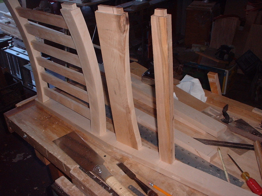
3. I started with the back legs, since they are one of the few pieces that need to be shaped into something more complex than a rectangle. On the prototype, the back legs are two inches wide and the front legs are 1 ¾ inches wide. I will admit that this was a mistake – it was all supposed to be 1 ¾. This is a pretty non-critical dimension, and the chair might look better if the legs were the same size. Note that it could be either size, as well. Clearly the chair will be longer front to back if the legs are all two inches wide, but only by half an inch (as compared to making them all 1 ¾ inches wide). You lay out the legs as follows. Start with a 36 x 4 1/2 inch board and ensure that it is the exact length and width and the edges are square and parallel. You may need to work around flaws in the board, but choose an end to be the bottom. Starting from the right side of the bottom end, measure over to the left your desired LW (Leg Width), say two inches, and make a mark which we will call point A. Now measure up 19 inches along the right edge, as we want the break (where the leg angles back) to be an inch up from the top rails. Make a mark at the right hand edge, which we will call point B. Using a square, run a line in from the edge at 90 degrees from point B. Measure in from the right hand side LW along this line and mark this point as point C. Join the two points A and C to form a line parallel to the right hand edge and LW over. Now, draw a line from point C to the top left corner of the board. This is the part of the chair that will support your back. Next, measure in from the top left corner LW, and mark this as point D. Draw a line to connect points B and D. This line should be exactly parallel with the last line you drew up to the top left corner. If it is not, read the directions again and try to figure out where you went wrong. Note that the width of the board you start with and the chosen leg width determine the rake of the back (the angle at which it leans back). On the prototype, I started with a four inch wide board and did not get enough rake for me to be comfortable. Thus, I changed the dimensions of the rough stock to allow for more rake. This type of chair often uses a 95 degree angle (i.e., five degrees back from vertical) as the rake angle for the back. My prototype chair exceeds that a bit, as trigonometry tells us the that a five degree angle over a 17 inch run gives us a bit under 1.5 inches. Still, even two inches did not feel right to me, which only proves that comfort is very subjective.
4. There are a few ways to cut out the resulting back leg shape, depending on how your shop is equipped. A table saw is probably the worst choice, since it is very hard to estimate how far you have cut as you cannot see the bottom part of the wood where the blade is widest. A band saw would probably be the best choice if you have one. You could make do with a jig saw if you are good at using one, and it is certainly possible to use a hand saw (either Western or Japanese) to cut out the shape. I tend to use a combination of tools, leaving a little margin of waste for planing the wood to exact dimensions later. The outside is easy to plane, and the inside is somewhat difficult. A chisel plane helps, as it is difficult to plane into a slight corner from two directions. I use chisels and spokeshaves for this job. Alternatively, you can make the break be rounded instead of angled, and it will be a bit easier. it might look better to you, but it is not really a “Mission” look as much as intersecting straight lines.
5. Once you have the back legs cut to the proper shape, it’s time to lay out the mortise holes. It this is the first chair, you will now make a story stick to determine the layout. (If not, proceed to step 6.) The most important thing is to be consistent in layout. It wouldn’t be a tragedy if a rail was half an inch too high on both legs that it connects, but it would be a tragedy if it was half an inch higher on one end than the other. It is all too easy to make a measuring mistake when using a tape measure or rule. With a story stick, you only have to get it right once; after that, all measurements are transferred directly from stick to component without the likelihood of reading the measuring device wrong. For this chair, there are six mortises in each back leg and four in each front leg. The front legs mortises duplicate the back leg ones, so we will layout all the back leg mortise locations on the story stick and use some of them for the front legs as well. I took a thin strip of maple five feet long and used it to lay out all the mortises. There are three sets of marks needed – one set for the narrow sides of the legs, which are mortises for the side rails; one set for the wide sides of the legs, which are mortises for the front and back rails; and one set for the back support assembly in the upper part of the back legs, also on the wide inner faces.
The rail mortises are all referenced from the floor, so make a mark on your story stick a few inches from one end to represent the floor reference. Label this set of measurements as “side rail – narrow.” Then make a line 8 ½ inches from the reference and another 1 inch further. This defines the mortise for the lower side rails. Measure 5 ½ inches from the last line and mark a line, then make another line at 2 ¾ inches further. This defines the mortise location for the upper arched side rails.
Reverse the story stick, keeping the same side up but using the other end; make a reference line for the floor. Label this “front/back rails – wide.” Measure up 10 ½ inches from the reference mark and draw a line, then make another one inch further. This is the mortise for the lower rail. Note that it is higher than the one for the side rails. Now measure another 3 ½ inches from the last line and make a line at this position. Finally, mark another line 2 ¾ inches further to define the top rail mortises. Note that the top rails do line up (otherwise the chair would look very odd) although the bottom rails are offset in height.
Now flip the story stick over and make another reference line, this time with the label “back support.” The back support is measured from the top of the back legs, so we always reference one end of the back leg. Clearly, it is very important that the two back legs be exactly the same length for this reason. Make a mark ¾ inch from the reference and another 1 ¼ inches further on. This will be the top back support mortise location. Measure 12 inches from the last line and draw another line, then another 1 ¼ inch further. This will be the bottom back support mortise.
6. Now it is time to actually lay out the mortises on the legs. Examine the legs to determine how they will be used in the chair. Typically, you would want the best sides out, as the outside is more visible. Figure out what will look best and mark the bottoms of both legs to indicate which is left and which is right, from the point of view of someone sitting in the chair. You will now mark the location of the side rail mortises on the front of both back legs. Find the part of the story stick for marking the side rail mortises (narrow set) and line up the bottom of each leg. Transfer the mortise marks to the leg pieces. These mortises are centered. If you are going to chop the mortises by hand, then set a mortise gauge to the width of your chisel and set the fence of the gauge so that it is half the remaining width of the board. So, if your board width was 13/16 inch and you were making a 5/16 inch mortise, you would set the fence to be ¼ inch from the closest point. For these rails, which are flush with the legs, it is very important that you get the centering right, or else they will not line up properly. If you are using a router to make the mortises, you probably have some jig or other mechanism for centering the router on the edge and will only need to mark the elevation. Next, mark the mortises for the front and back rails on the inside of the back legs. Transfer the elevation marks from the appropriate end of the story stick (marked wide) to the inside back legs. You now know the height, but these mortises are not centered. Set your mortise gauge to 3/8 inch between points and 3/8 inch from the fence to the closest point. The rails are offset to the outside of this chair, so you will reference your gauge to the back surface of the back legs. Mark the mortises between the elevation lines for the top and bottom rails. You may have some difficulty with the top rail due to the gauge hitting the part of the back leg that angles back. If so, mark most of the top rail mortise and then extend the line formed by the gauge point with a ruler and marking knife. Finally, mark the back support mortise locations on the top part of the back legs from the story stick. These mortises are ½ inch wide and centered. For a 1 ¾ inch wide leg, they can be marked as 5/8 inch in from the front edge of the back legs. For a two inch wide leg, ¾ inch would center the back support, but you might find the 5/8 inch offset more aesthetically pleasing.
7. Now, you get to chop the mortises by hand or make them with a router. Of course, you need to know how deep to make them. The mortises on the narrow edge – the front of the back leg – can be made 1 1/16 inch deep, and the lengths in the cut list assume this. Mortises cut into the wide face of the board can only be ½ inch deep. Be very careful if you are using an auger to remove wood as part of making the mortise. Clearly, you don’t want the pilot part of the drill bit to pass through the outside face of the chair leg.
8. Once you have finished the back legs, it is time to make the mortises in the front legs. These are pretty much the same as the ones on the back legs, but of course there will only be mortises for the rails. On the prototype chair, I made the top of the top rails flush without a top shoulder. This is more visually interesting (perhaps) as you can see the joinery where it projects right through to the top of the front legs. It does, however, make things more demanding, as you now have to make perfect mortise and tenon joints. Also, there isn’t quite room to do this with both the front and side rails, so I have changed the design to eliminate this feature. I now make all joints the same, with about a ¼ inch shoulder on top and bottom. Lay out the top and bottom rail mortises as you did for the back legs, then chop or route out the mortises using your favorite method. Be careful since you are working only ¼ inch from the top of the front legs, though. There isn’t much room for error here.
9. Now that you have completed most of the easy parts of the chair, it is time to turn our attention to the parts with curved surfaces. I will describe the very complicated back support assembly first. We will then move on to the arched top rails, which will seem easy in comparison. The back support assembly consists of upper and lower curved rails plus six slats that connect them. Once completed as a sub-assembly, the entire back support will then be inserted into the mortises that were formed in the upper part of the back legs. The hardest part of this construction is forming two curved boards from two straight boards. The initial problem to be solved (happily, you only have to solve it once) is to make a template for the curve. I made mine from thin (1//8 inch) plywood as it will be sturdy enough for reuse. The thickness of the back support rails will be one inch when we are done, which means that the radii of the two curves must differ by one inch. Otherwise, the curves would intersect. You could choose to make the rails slightly thicker if you find this visually appealing, but then you would need to adjust the inner or outer radius as appropriate. The prototype chair was made with an outer radius of 36 inches and an inner radius of 35 inches. It is unlikely you have a compass this large in your shop, and when you get to the arched top rails, even larger radii will be required. So before you even make the template, you need to make a beam compass from a piece of scrap wood about five feet long. Measure in from one end a few inches and mark a spot for the pencil. Now measure 36 inches from that point and make another mark. It is now safe to drill out the pencil hole. You should choose the diameter such that a pencil will fit snugly, and not fall out as the board is moved around the shop. The 36 inch mark can be used as a reference for all other dimensions, since it is more difficult to measure from the middle of the relatively large pencil hole. Make another mark one inch closer to the pencil for the inside of the back support rail template, assuming you have chosen a one inch thick back support. Drill very small pilot holes at the two marked points, and drive a nail through one of them. Clamp a piece of plywood big enough to form the template (the curve should end up at least 18 inches long, and 24 would be better) on your bench, and another scrap piece of the same thickness three feet away. Place the beam compass on your bench with the nail end on the scrap piece and the pencil end on the template material. Ensure that you can get a good enough swing to mark the size arc you need. Lightly drive the nail into the scrap just enough to keep it from falling out, and then scribe an arc with the pencil on the template board. Now, without disturbing either piece of plywood, remove the beam compass, pull the nail, and drive another nail into the other marked spot one inch away from the first nail hole. Replace the beam compass so that the nail is in exactly the same hole in the scrap. You can now scribe another arc, which should be parallel to the first arc but one inch away. Remove everything and save the scrap and the beam compass for later steps. Using whatever method you find most appropriate, cut out the back support template from the piece of plywood and make sure the edges are smooth and parallel.
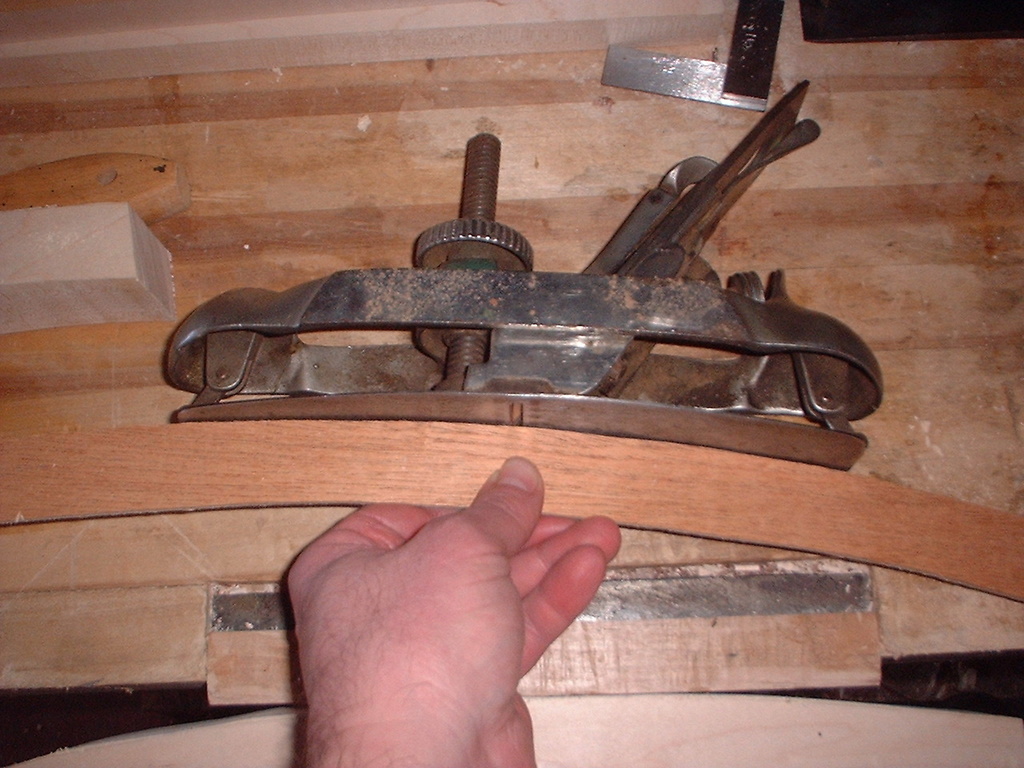
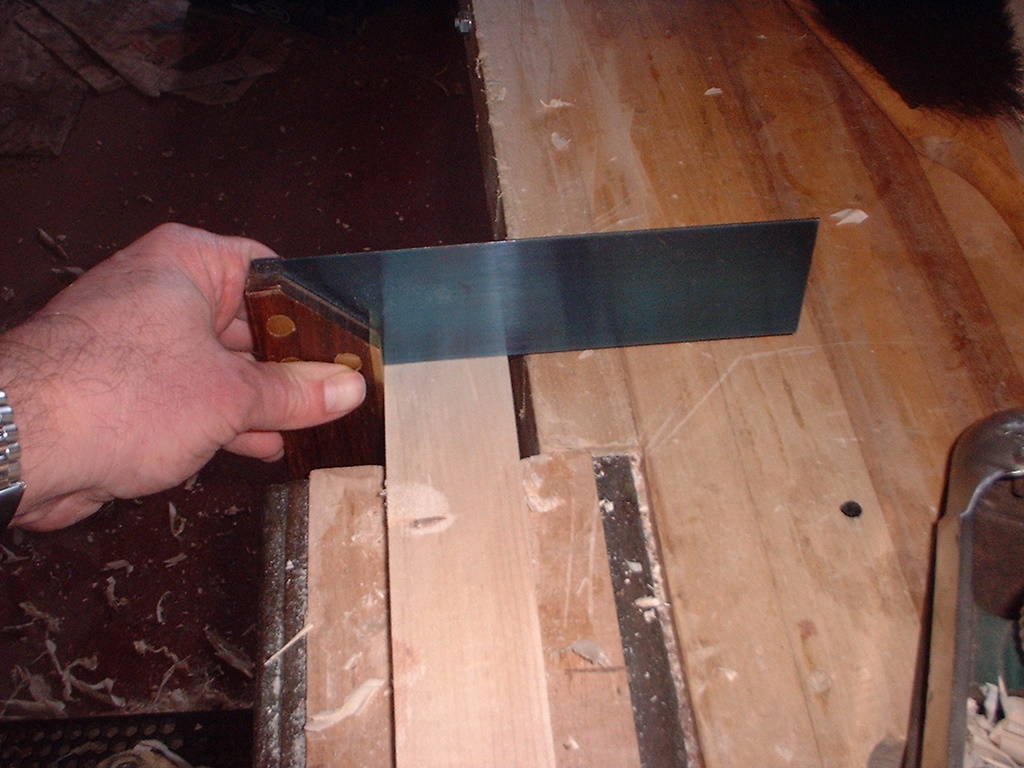
10. As noted in the cut list, I like to cut both back support rails from one piece of wood, as it is more efficient. Place the stock on your bench with a wide side parallel to the bench top. If the board has flaws, it is useful to consider which layout will give you the “best wood” after the scrap is removed. Place the template from the previous step on top of the board and mark lines on both edges. You should orient the template so that the distance from an arc to the edge of the board is the same on both ends; i.e., don’t try to draw the arcs diagonally, since the board is dimensioned to allow you to cut two straight tenons on the ends. Repeat with the layout of the other back support rail. It is a good idea to mark the tenons at this point as well, since it will be harder once the board is no longer square. Now use whatever means you have at hand to cut along the scribed arcs to give you the resulting curved rails. A band saw works well here, and a good quality jig saw could work as well if you are careful to cut at exactly 90 degrees. If you prefer hand tool methods, a bow saw or coping saw would work, although the material may be a bit thick for the latter. You can also saw straight down and subdivide the curve into small segments, then remove them with a chisel. Regardless of method, you will need to clean things up when you are done. A circular plane like a Stanley #20 is a great help here. You can set it to the template (see Fig.) and plane the outside and inside curves. Pay particular attention to grain direction here. Sometimes you will have to plane from the center towards the ends, and sometimes from the ends to the center. If you used a band saw and got a very accurate cut, you may be able to skip the planing step (especially if you don’t own a circular plane) and just use spokeshaves to clean things up. The Millers Falls “cigar shave” is the ideal tool for the inside curve. Almost any spokeshave will work well enough on the outside curve. The important thing here is to ensure that the curves are not only smooth but also that the cleaned up surfaces are square to what will be the top and bottom. Check frequently with a square during this process to make sure that they are (see Fig).
11. At this point, we need to lay out the locations of the slat mortises. For this chair, I divided the space up so that it is about “half wood, half air.” The slats are 1 ½ inches wide, and so are the spaces between them. Of course, the mortises will be smaller than the slats since the shoulders will overlap some. The actual tenons will be 3/4 inch long, 3/8 inch wide, and ¾ inch deep. Since you already have a template, it makes sense to just mark the template as a story stick and use it to mark the back support rails for the mortise locations. As always, it is better to be consistent than exactly correct in position, as your eye will notice two slats out of parallel far more easily than two slats slightly to close or too far apart. I mark the template on the inside curve. Find the approximate center of the template and mark this as the center line. Now move out 7/8 inch to one side of the center line and make a mark. Move out another ¾ inch and mark another line; label this space M to indicate it is a mortise location. Now move out another 1 ¾ inch, make a mark, and move out ¾ inch and make a second mark. Repeat once more. Mark the two ¾ inch gaps with an M. Repeat the process on the other side of the center line. You should now have six spaces marked M for the six mortises. Now that you have your marked template, determine which back support rail will be on top and which on the bottom. The top one will be more visible, so if there is a quality difference you should choose the better rail for the top. Also, the top sides of the rails will be visible and the bottom sides will not, so put your best face upward. Label the orientation and position of the two rails. You will now mark the bottom of the top rail and the top of the bottom rail for mortises. Place the rail on your bench so that the surface to be marked is facing up, and carefully determine the center line of the rail itself. Mark this location on the rail, making sure the mark can be seen at the inside edge. Now place the template on top of the rail. Move it slightly back so you have a place to mark the rail and line up the center line on the template with the center line on the rail. Copy the marks from the template to the inner edge of the tail. Repeat this process with the other rail. Now, take a small engineer’s square and draw lines across the top of the rails at each mark. Since the rail is curved, the lines will not be parallel, but will diverse slightly. This is not a problem, since the tenon shoulder will overlap and non-parallel edges. Take your mortise gauge and set it for a 3/8 inch mortise 3/8 in from the fence. I like to mark the mortise locations from the inside arc, but feel free to use the outside arc or to adjust the offset to whatever appearance you find pleasing. I sometimes make my rails be 1 1/8 inch thick, so that a 3/8 inch offset results in centered slats. This is really a judgment call on your part to some extent. Once the mortises locations have been determined, chop the mortises by your favorite method. When you are done, cut the tenons on the ends of the rail. The important thing is that the space between the back legs will be exactly 16 ½ inches so the length between tenon shoulder must be exactly this amount as well. Of course, the tenons must be square or there will be unsightly gaps. These tenons must fit the mortises you already made in the upper back legs, so make tenon shoulders to fit those mortise holes as closely as you can and trim the shoulders for a gap-free fit.
12. After the last step, you are probably ready for something easy, like making tenons on the six slats. I saw tenon shoulders with a backsaw and a bench hook, but feel free to use whatever method you prefer. As always, the really critical dimension here is the distance between the shoulders, as this determines how far apart the back support rails end up. For this chair, this should be exactly 11 ½ inches. Of course, the real issue is that all six slats be exactly the same length in this dimension, or you will have gaps. If your tenon is too long you can cut it off, and if it is too short you can ignore the problem as it is inside the joint anyway. But if you inadvertently make the distance too short between the tenon shoulders on one of the slats, you just have to throw it away and make another. Note that the tenon shoulders on the wide part of the boards are quite narrow, only 1/16 inch for a ½ inch thick slat. If you don’t feel comfortable with such narrow tenon shoulders, you can either make the mortises narrower (1/4 inch instead of 3/8 inch) or use thicker stock (5/8 inch) for the slats. I just had a large amount of ½ inch stock in my shop and so designed things this way. The shoulders on the narrow faces of the slats are more normal at ¼ inch. Carefully mark and cut the tenon on both ends of all six boards. The ideal in cabinetmaking is to achieve a “piston fit” – when you insert a tenon in a mortise it should not bind but you should have to fight the air escaping from the hole. I certainly can’t do this every time, and don’t feel frustrated if you can’t do it at all. But you want the fit to be snug. If it flops around it is too loose, and if you need to whack it with a mallet to seat it, then it is way too tight. I make the tenons slightly oversize and adjust them with a shoulder plane until they fit properly. When all twelve joints fit to your satisfaction, you can clean up any surfaces that need it. It will be much harder to do so after you have glued things up, which is the next step. Make sure that the assembly is square by measuring diagonally both ways and ensuring the results are equal. Also, make sure that there is no twist to the assembly. It should lie flat on your bench with the concave sides of the rails down. If not, you may need to slightly adjust the joinery. When all seems well, go ahead and glue things up, using clamps as required.
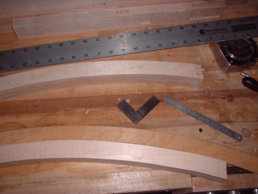
13. Now it is time to make some rails. There are two kinds – the relatively simple bottom rails and the arched top rails. Well, you probably know what’s coming by now. If there’s a curved surface, you need to make a template for it. I had some templates of the proper size in the shop from a previous project, but you won’t so it’s time to drag out your shop-made beam compass and some more thin plywood. Since the chair seat is not square, the rails are not the same length. To get the arches to look right, two different radii will be required. The side rails require a 46 inch radius and the front and back rails a 47 ½ inch radius. So retrieve your compass, pull out a nail if there is one, and drill pilot holes at those locations. Since you are referencing from the 36 inch hole, make one hole ten inches away from the reference, away from the pencil end. Then make another 1 ½ inches beyond the last one. Using the same procedure as before, make two templates from thin plywood and mark them to indicate which is for the side rails and which for the front and back. If you wish to save time, just make a single template with a 46 inch radius curve on the inside and a 47 ½ inch curve on the outside. This will work fine and you’ll have one less template to keep track of.
14. We only need the back rails for now, but you might as well make the front ones at the same time. That way, you will be less likely to make a pair that don’t match. Find the stock for the front and back rails, and mark the tenon locations. These rails go into the shallow mortises on the insides of the front and back legs. The stock is dimensioned to allow for a half inch tenon on each end, allowing you to saw a bit off the end when fitting if they are too long. The critical dimension here is 16 ½ inches between the tenons, since the chair is going to end up 18 inches wide. Mark and saw the tenons in all four rails (top and bottom, front and back) so that they are all the same length. Now place one of the side rails flat on your bench with the bottom edge (the one the arch will be cut from) towards you. Make a mark one inch in from each end; I usually mark right on the bottom edge itself, or right at the corner with the face. Take your template for the front and rear arched rails and line it up with these marks, then draw an arc to connect them. This will give you an inch of flat space at each end of the board and an arch in between, which is the look I want for this design. Of course, you are free to adjust it if you wish. Cut out the arch by your favorite method (band saw, jig saw, coping saw, etc.) and smooth the curve with spokeshaves. It’s a little thin to use a circular plane on. Repeat for the front arched rail. When you are finished, do a final cleanup on all four rails, and select the two rails that will be used for the back.
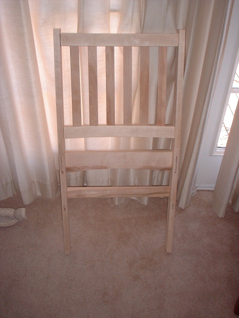
15. Now, fit the tenons for the back support assembly and the upper and lower
back rails for as good a fit as you can. Test fit the back leg assembly to
ensure it is square and co-planar. Clean up the back legs as necessary. As
always, it is easier to make boards ready for finishing before they are glued
up. When you are satisfied, glue up the whole back leg assembly and set it aside
to dry. The front leg subassembly is a bit easier than the back, as there are
only four joints to fit. Make sure the front legs are cleaned up, then glue up
the front leg assembly so it is square and co-planar. Make sure the tops of the
upper rails are flush with the tops of the front legs. Set this aside to dry.
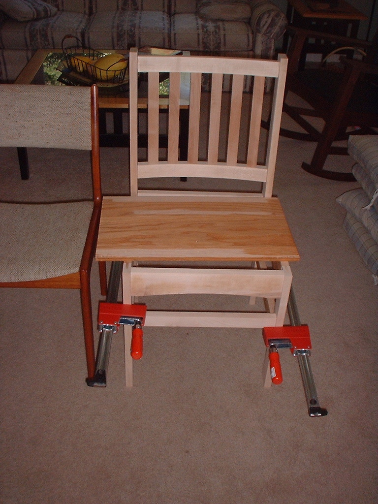
16. Make the two side rails using the same technique as was used for the front and back rails. Since these go into the long sides of the legs, they have to be shorter in between the tenons. (note, however, that the tenons themselves are longer). The critical dimension for the side rails is 14 inches between tenons, with nominal one inch tenons on each end. It’s a good idea to assign the side rails to the left or right side of the chair, based on any flaws or odd grain patterns that you want on the inside. Mark the rails left and right, and make sure the letters are written so that they are right-side up when the top of the rail is up. Form the tenons on all four side rails. Now, mark one inch in from the tenons on the top rail along the bottom edge and mark the arch with the 46 inch radius template. Cut out the arch and clean it up with spokeshaves, sandpaper, etc. Now carefully fit the mortise and tenon joints with the front and back leg assemblies. When everything fits properly and the shoulders are square and produce clean joints without gaps, clean up the rails with a smoothing plane, scrapers, sandpaper, or your favorite method. Now you are ready to assemble everything. On the prototype chair, I dry assembled the whole chair, clamped it front-to-back, and placed some plywood over the seat so I could sit in it and see if everything worked. This is how I found out that the chair back did not have enough rake for me to be comfortable, but there was nothing I could have done about it at this point except to make a new back leg assembly. At least it is an opportunity to ensure that everything is square and fits properly. When satisfied, take everything apart and glue up the joints. Clamp and set the assembly aside to dry. You can do the next step while the chair is in this state.
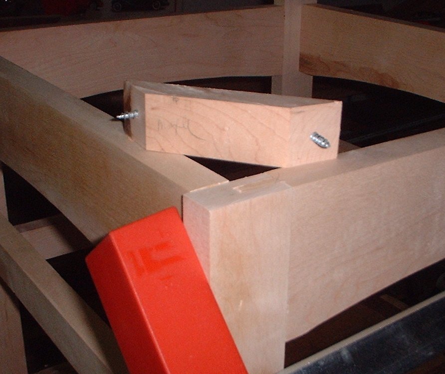
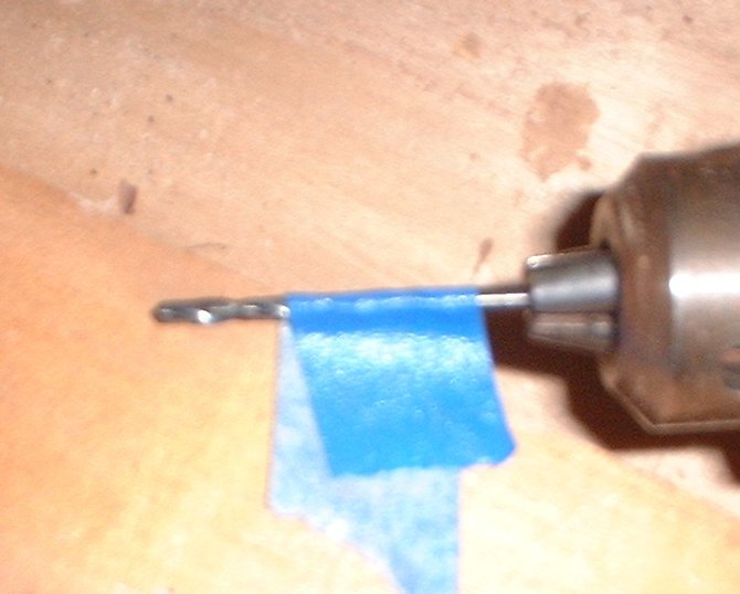
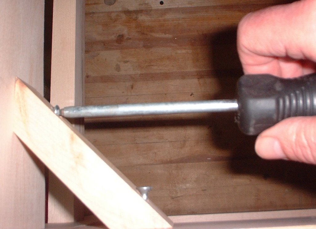
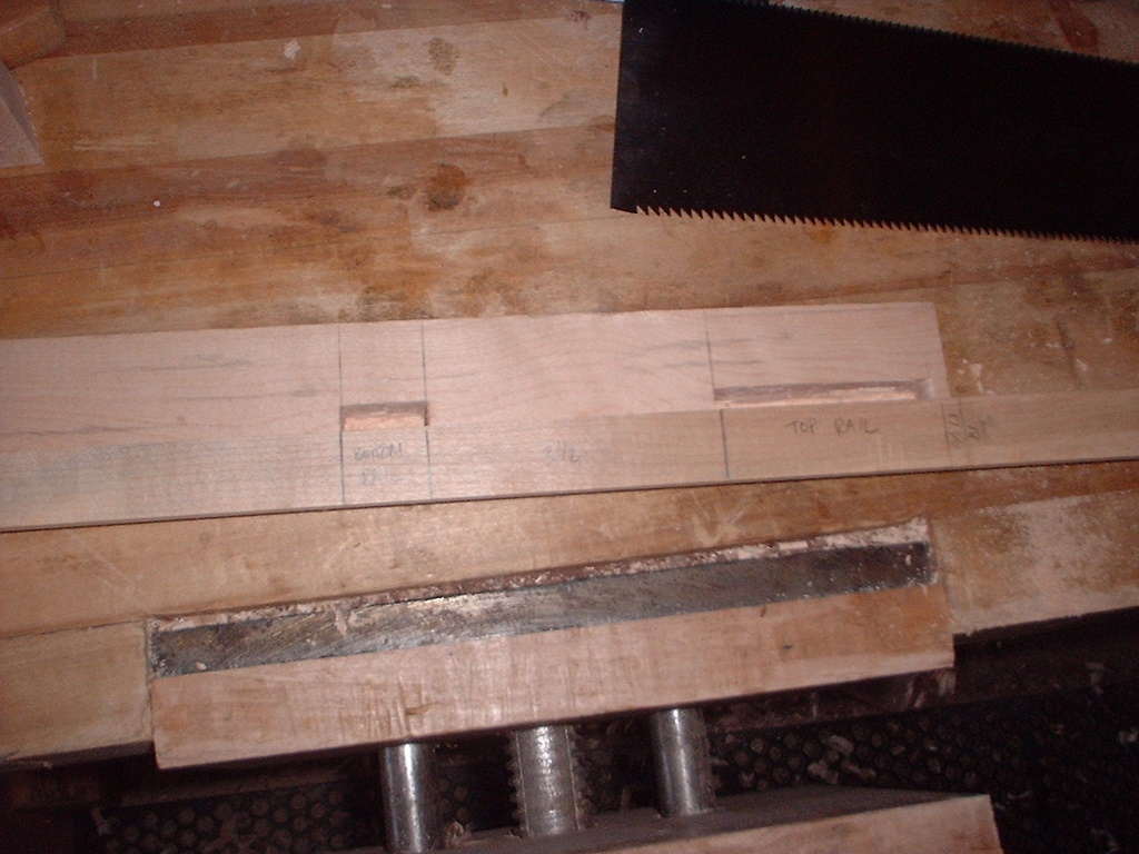
17. There should be enough scrap saved from previous steps to make four diagonal corner braces or support brackets. The brackets serve two functions - they support the seat, and they resist the racking stresses that all chairs are subject to when people sit or stand. These braces are 4 ½ inches long and beveled at 45 degrees on both ends. When placed in the corner of each chair (between the arched top rails), the wider face is vertical; make sure you cut them this way (see first picture, above). They are easily cut on the table saw by tilting the blade to a 45 degree angle and cutting off pieces from a 1 ¼ inch wide piece of stock, flipping it over on every cut. You could just as easily use a miter box if you have one. I use a miter trimmer to clean them up, but if you own a chop saw it would probably work just as well for this operation. I then drill and countersink in the middle of the bevels. This takes some getting used to, as you are drilling from the opposite side. I place each corner piece on the drill press table bevel-down so that the piece is sticking up in the air at a 45 degree angle. Drill a hole with a countersink bit about three quarters of an inch in from the mitered edge and centered left-to-right. It isn’t critical, but by the time you do the eighth bevel, you should be hitting dead center of the bevel face. Unfortunately, the people who make countersink bits don’t know much about wood screws; the bit is always too small. Ideally, you don’t want the screw threads to engage the top piece at all, or tightening the screw will tend to push the pieces apart rather than together. You should be able to push the screw through the hole in the top piece without any binding, so re-drill the holes with a 3/16 inch bit, the right size for a #8 wood screw. To install these corners, place them in the corner formed by two adjacent arched rails and locate the top one inch down from the top of the rails. I like to mark the location by pushing an awl through each screw hole to mark the desired spot, then drilling a 3/32 inch hole half an inch deep at that location. I use a tape flag on the drill bit (see middle picture) to keep me from drilling through the outside of the rail. Screw the brackets in to the rails with the #8 wood screws. The chair seat will sit on top of these brackets. If you are really concerned with strength due to large visitors or teenagers who like to rock back and balance on chair legs, then consider making the braces two inches high and using four screws per brace instead of two.
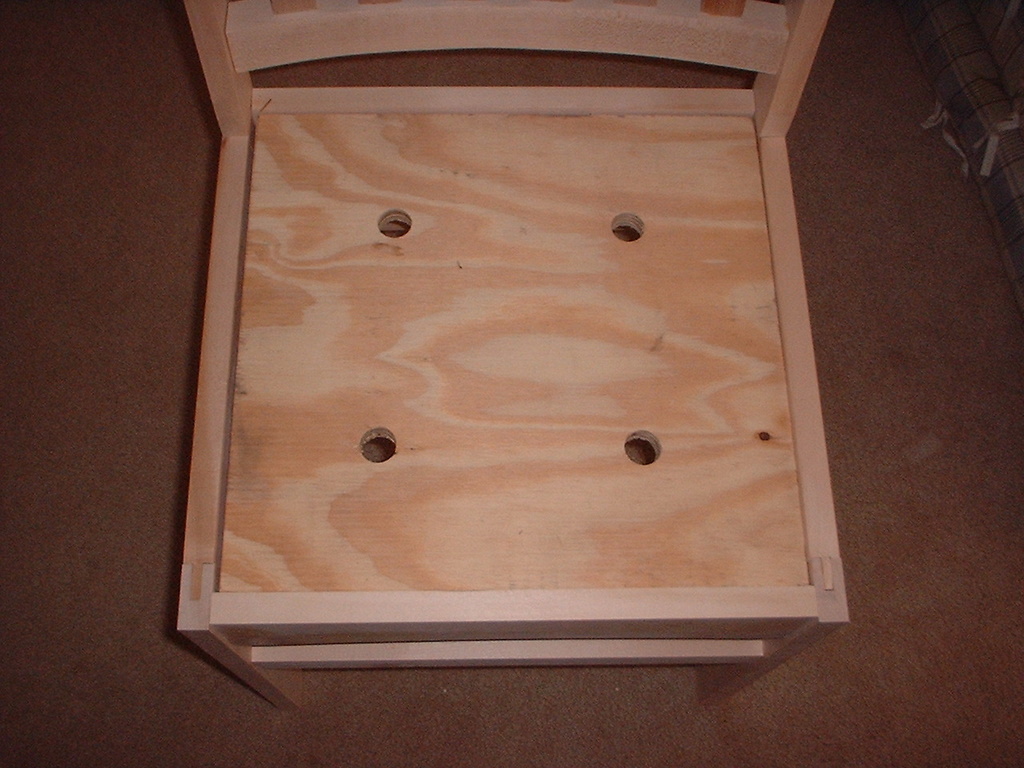
18. Now measure the opening for the seat between the pairs of arched rails. Take a piece of plywood and cut it to these dimensions minus about 1/8 inch. When installed, you want to leave 1/16 inch on all four edges for the fabric that will cover the seat. This chair is rather easy in that all corners can be square. On some chairs with legs that protrude into the opening, you need to cut off the corners at a 45 degree angle to allow for the inward-projecting legs. It is useful to bevel the top edges of the seat plywood at a 45 degree angle. Also, when someone sits down in the chair, there needs to be someplace for the air to go as the foam compresses. I drill four one-inch diameter holes in the plywood about six inches in from the corners for this air passage.
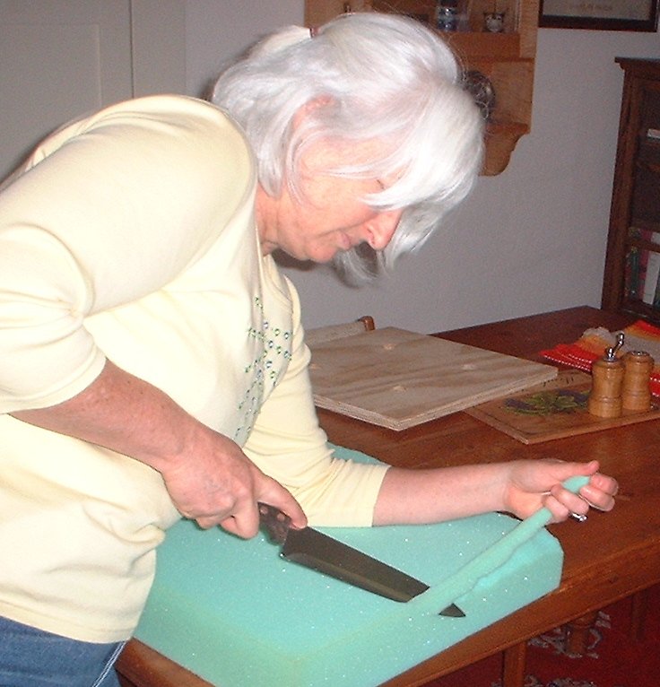
19. Next, cut the upholstery foam to the same dimensions as the wooden seat
you made in the last step. Bevel the top edges of the foam to a 45 degree angle
– a kitchen knife works well for this, as upholstery foam is quite stiff. If you
can’t cut the foam with a knife, there is a good likelihood that you have
obtained the wrong kind of foam. Real upholstery foam is very stiff, and will
not compress except under significant pressure, as we will do in the next step.
It comes in several thicknesses, but three inches seems to be about right for
these chairs. If your are building a chair where the seat overlays the front
edge, you might want to use two inch foam. Here, the front of the seat is inside
the rails and the extra height keeps the bottom of your thighs from touching the
sharp outside edge of the front top rail. When you have finished with the foam,
cut your desired material to the size of the chair blank plus about four
inches on each edge. A 24 inch square piece will work quite well here.
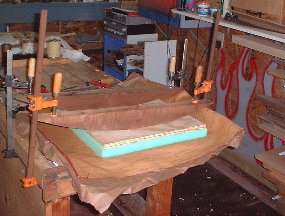
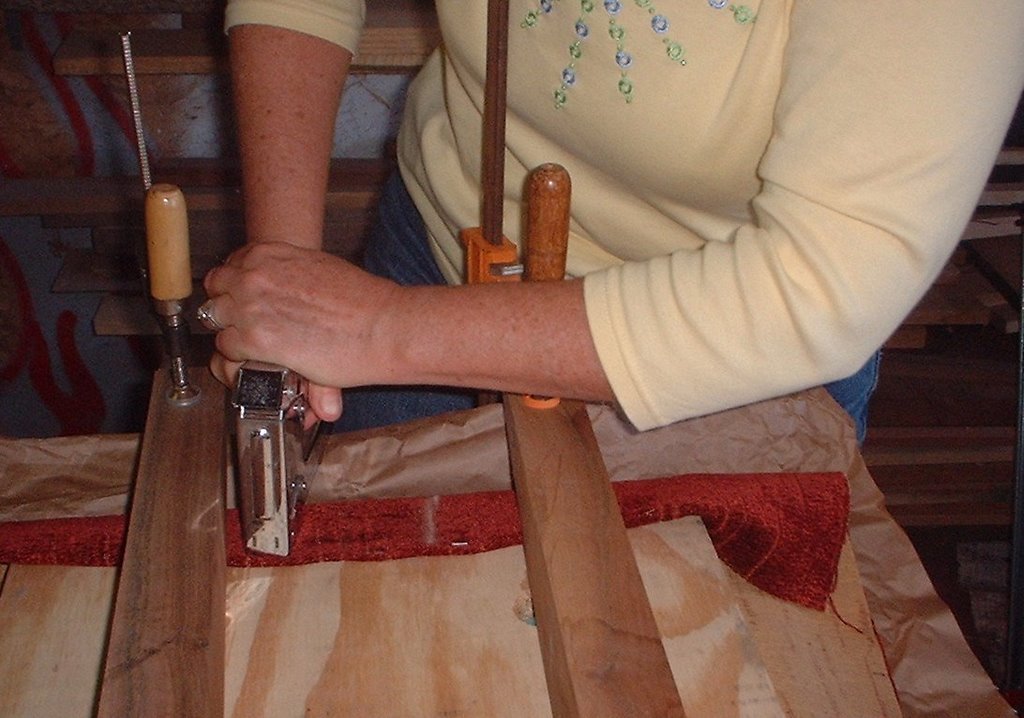
20. Now, ensure that you have a place to assemble the seat. It must be at least as big as the seat blank, and must be able to withstand considerable clamping pressure. Don’t use your dining room table as it does not meet the last criterion. I tried this once and had to spend considerable time repairing the table. I now use the top of work bench, which is 2 ¼ inch thick poplar and can take the pressure without flexing. Since it is often dirty, I place a piece of butcher paper or something similar on the bench first to keep the cloth clean. Next, place the cloth with the good face down, followed by the foam with the beveled side down, and lastly with the seat blank. Make sure everything is well centered. Now, you are going to clamp this assembly to the bench top until the foam compresses down to about 1 ¼ inches. There are several ways to do this successfully. In the pictures above I used cauls that are scrap walnut left over from a rocking chair. The curved surface faces down and exerts pressure in the middle of the seat so you can still work around the edges; the flat top makes clamping relatively simple. The cauls have to be long enough so that you can get clamps on them, which in my case means 24 inches to match the bench top width. If you don’t have something like this around, I would not bother to make some. You can do just as well with a small block of 2 x 4 under a two foot long piece of wood. The block localizes pressure in the middle of the chair blank, which is what you want. Using two clamps on each board (you could make do with one board in a pinch, but two distributes pressure better), tighten the clamps evenly until the foam has compressed the correct amount. Now bring each edge up and fasten the material to the seat blank using either upholstery tacks or staples. If the material is thin, I like to fold the edges over and staple through them as shown above. Work your way from the center out on all four edges, leaving a few inches near the corner. You will now need to cut the material that has bunched up in the corners so that it can be made to lie flat. Essentially, you cut off the extra length until you have two edges that are parallel and run in at a 45 degree from the corner. There should be some overlap left – don’t remove so much that there is a gap. Fasten this down as you did the sides. When done, you can release the clamps and remove the cauls. The seat should fit into its opening without excessive force, but you should need some pressure to get it in place.
21. Now you can sit in the chair and see how the height works with the seat
installed. I deliberately make the legs long so they can be trimmed. As always,
it's a lot easier to make something shorter. While this chair can be left
perfectly square, you may find it is more comfortable with a little backwards
tilt. Many chairs are designed this way, although sometimes it is so subtle you
don't notice it. You can experiment with this by simply inserting a wide board
under the front legs and see how it feels to sit in the chair. Of course, your
feet may not reach the floor, but you can ignore this - you are only testing how
your back feels. To make the chair lean back a bit, you will simply make the
rear legs shorter, not make the front legs longer. If you found that the chair
was too high without the board, you can easily adjust the height and add some
"lean" at the same time by drawing a straight line at an appropriate level. For
example, if your feet barely touch the floor when the chair was level and you
like the chair slightly tilted, make a line 1/2 inch up on the front of the
front legs and one inch up on the back of the back legs. Connect these two
points with a straight edge and saw along the line. Repeat for the other side.
Be a bit conservative here, since you can't put the wood back if you take too
much off. When the chair is to your liking, you will probably want to install
some glides on the end of the legs, especially if you have wood floors. Remember
that these will add a little height to the chair.
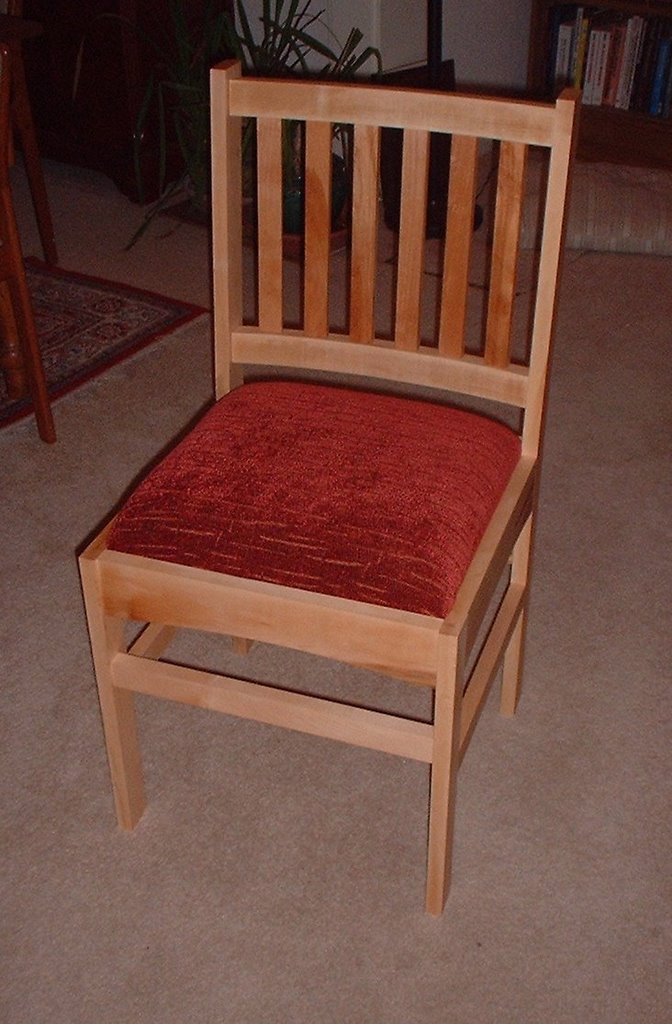
22. Finally, remove the seat and finish the surfaces of the chair as desired.
You have mostly planed, scraped, or sanded everything before assembly, so this
should be relatively quick. I finished this chair with a Danish oil mixture with
no tint, as I wanted the natural color of the maple to be preserved as much as
possible. Of course only you (and your family) know what the desired final
“look” of the piece is supposed to be, so choose a finish that works well with
the contents of your home.